Adsense review

Sunday, May 25, 2008

Door Braces

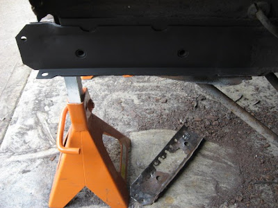
With the completion of the repairs to the forward area of the car, it is now time to work on the real problem areas. Namely, the structural members such as the torque boxes, inner rockers, and floor pans. The problem is that since these are structural members, the car will be weakened by their removal and the car would be at risk of bending at the bottoms of the door openings essentially folding up on itself. Needless to say, this would be bad.

An extreme solution would be to put the car on a frame jig, an assembly of dimensional steel that takes over the total support of the car. Since I intend to take a more surgical approach by repairing one side at a time and not removing large sections of the floor immediately, I'm going to attempt to get by with a set of door braces to prevent fold-up, and cross members to prevent twist.

I had done some prior research into the construction of door braces. Initially, I was going to purchase some rather nice looking universal door braces from Accessible Systems. However, $300 plus around $75 for shipping seemed like a waste of funds to me. I could get a set of used disc brakes for the front for that much or a power steering unit or a multitude of after-market parts so I opted to attempt to design my own based on those from Accessible Systems and from Kevin's Rod Shop.

$71 later, I had procured 3 8 foot sections of 1/2" solid square bar steel and a couple of 2 foot sections of 1/8 flat steel from my local hardware store and set to cutting and welding them into something that loosely resembles a set of door braces. I cut 6 3.5" x 3" chunks of flat 1/8" stock and drilled holes to match the door hinge bolt locations and door striker bolt locations. From there, I tacked 2 4' lengths of square bar between the 2 hinge plates and the door striker plate on each side. I tacked 3 shorter sections of square bar to tie the long bars together.
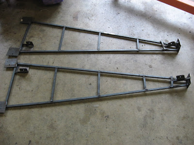

I "felt" that I needed to reinforce the door striker side of the braces with a kind of a tri-pod configuration. Finally, I welded in some flat 1/8" brackets at each end of each brace with 5/16" holes drilled in them to mount the cross members to in order to prevent the body from twisting while I'm working on the car.
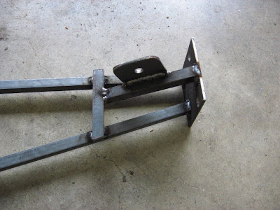
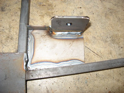

I found a couple of lengths of bed frame I had laying around in my back yard and cut them and drilled them to mount to the brackets I had previously welded to the door braces. I chose to bolt these sections on to make removal of the braces easier and to allow me to use a "brace to tunnel" support system in the event that I decide to replace the floors on each side rather than the entire floor which I'm still undecided.

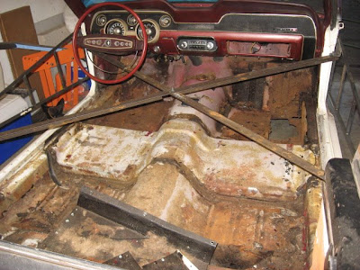
So now I'm ready to raise the car up onto jack stands for disassembly and repair of the floors!

Monday, May 19, 2008

Left Front Outer Frame Rail Patch

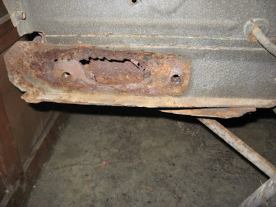
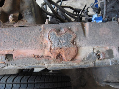
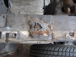
I took the day off from work today to celebrate my birthday (thanks Dave!), and felt the need to try my hand at frame rail repair. You see, when I was disassembling the car to take to the shop, I removed the left front bumper bracket from the frame rail. The bumper bracket was rusted out and had left some rust scale behind on the frame rail so I pulled out my trusty air chisel to clean it up and clean it up I did! The center of the frame rail between the mounting nuts, popped off in in hand to the tune of various expletives. The Mustang shop guy told me that this was normal damage... for the passenger side under the battery tray due to the corrosives that come from the battery but he'd never heard of this happening to the driver's side. Weeeelll, paint me pink and call me Shirley, ain't I lucky!? Here's how I decided to tackle the problem:
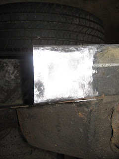

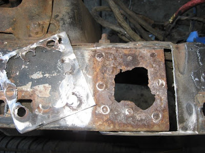
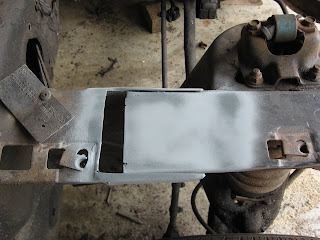
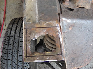
This is what we started with. Looks scary, better total out the car right!?
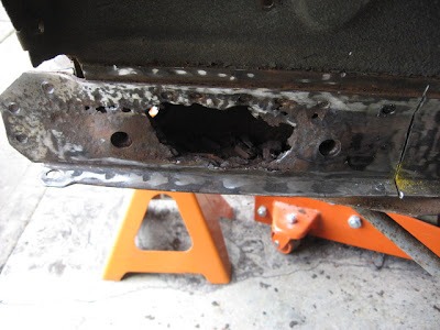
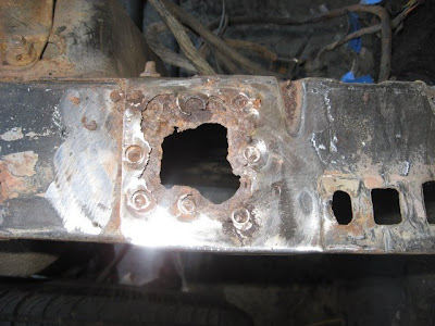
Bah! I have a 4.5" angle grinder and I'm not afraid to use it! First we gotta clean up the area to ensure the rust stops at some point. I chose a line in front of cross member that attches to the bottom of the rail and between two spot welds top and bottom and cut the slot. I used my sawz-all to finish the cut on the bottom flange. Also, at this time, I noted the location of the captive nuts on the area above the frame rail so I could ensure that the horizontal alignment of the holes of the new part are identical to the old.

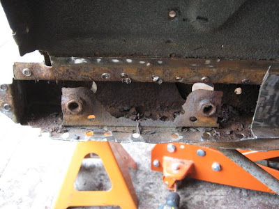
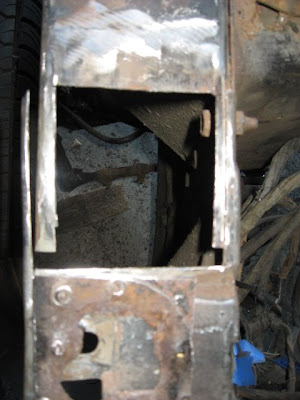
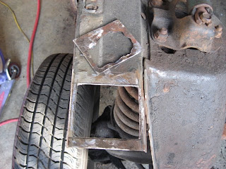
I drilled out all of the spot welds and popped the old outer rail off with the air chisel. Now, the repro frame rail I bought to patch this has captive nuts welded to the rail itself so you have to imagine my surprise to see this bracket welded into the frame. I certainly was not expecting this. I thought the captive nuts were welded to the outer rail like the repro rail. I determined that this bracket was partially responsible for the deterioration of the rail since it left lots of places for water to get in between and no way to drain or evaporate.

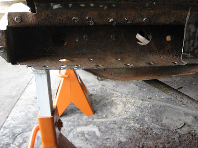
4 spot welds were holding it in so I cut those welds and air-chiseled it out. I considered briefly to fab a new bracket but decided against it because I don't have any better way to seal the bracket to protect it from moisture (other than paint) than Ford did in 1968. Plus I'm not setup to fabricate sheet metal parts with tight bends out of metal as thick as 14 gauge. I ground the inside of the rail as much as I could reach with my tools and then treated it with Jasco Prep & Prime, and then sprayed primer on as much interior rail as I could get to and finally, treated the weld surfaces with weldable primer.

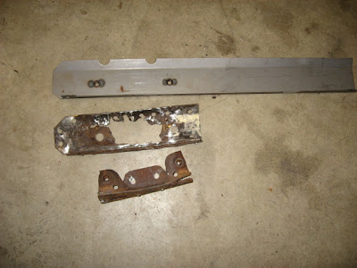
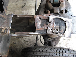
This is the repro frame rail patch with the old rusted parts. I cut out the new patch by measuring against the hole locations I took in the above step and the vertical cut from the car where the old rail was cut out.

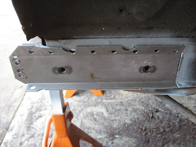
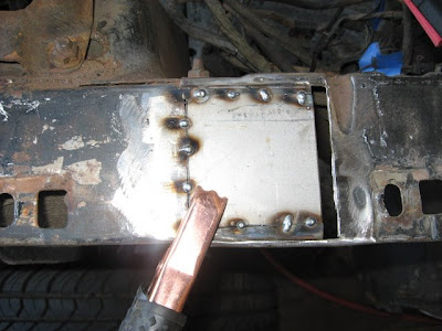
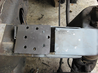
Here is the preliminary fitting of the new patch. I've predrilled all of the plug weld holes and have adjusted the angle of the upper flange using the precision "smack it with a hammer till it fits" methodology. Also, the front edge of the patch had to be straightened flat to mate with the front frame rail.

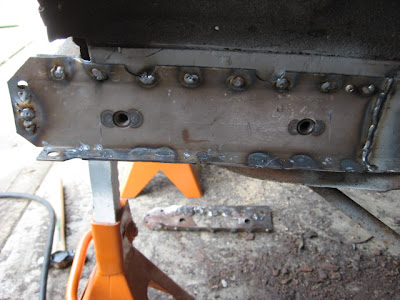
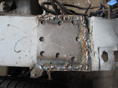
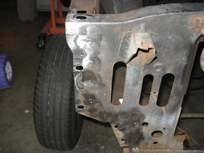
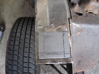
I used clamps on the bottom flange and sheet metal screws on the upper flange to draw the outer rail patch to the inner rail and made tack welds all along the patch until it was tight (along with some strategically placed hammer blows). Finally, I finished the plug welds and welded the patch to the existing outer frame. My new birthday present really helped a lot on this step.

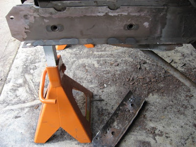
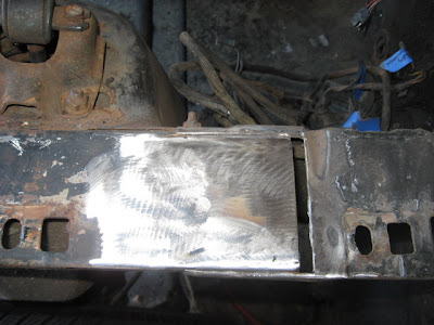
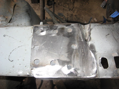
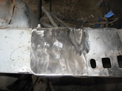
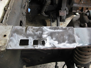
The welds were ground down flush...


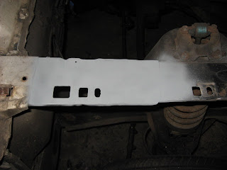
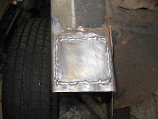
...And then primered for that not-so-rusted look. Note the old, rusty, frame laying dejected on the ground never to see the road again.

A Birthday Present

Being that today is my birthday, I decided to buy myself a new birthday present.

I had been struggling with my welds because I kept losing my starting point between placing the MIG wire in the position where I wanted to start my weld and putting down my welding helmet resulting in missed tack welds and/or wavy, uneven weld beads. I tried the "close your eyes to tack" trick and flashed myself a couple times in the process.

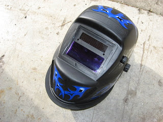
I got my Harbor Freight ad the other day and saw that they had an Auto-Darkening Welding Helmet on sale for $49. I was a bit worried about cheap Chinese equipment destroying my only set of eyeballs so I did some googling and found what I figured I'd find. Several guys saying they love their HF helmets and several guys saying that they would never risk their eyes to "Chinese Junk" and swore by their $400 Jackson helmets. However, I found very few complaints about the HF helmets other than "if you drop them, they will die". I also read that even if you do get flashed, the lenses in these new helmets will stop most all of the damaging infra-red radiation with the worst damage being the flash-bulb affect. So, given this fact, and the fact that just because you buy something from Sears for twice as much, it doesn't guarantee it's not made in China anyway, I decided to give this helmet a try:


I used it for the first time today on today's task patching the left front outer frame rail and it worked GREAT! I set the helmet to "high sensitivity" and "long lightening delay" (meaning that it waits for a short delay after the arc stops to re-lighten the lens) in addition to the "shade" setting at 12. When no arc is present, the lens is like wearing lightly tinted sunglasses. When just the first 1/25000th of a second of spark from the welder is seen by the 2 sensors, the lens goes to your selected shade of darkness (up t0 14). Also, the battery in the helmet is charged via the solar cells by the welder's arc! (the strip above the dark lens). The purpose is to allow me to see the MIG wire right up to the moment the welder draws and arc resulting in cleaner, straighter welds. BTW, you can test the helmet by looking away from the arc while striking the weld and ensuring that the lens darkens appropriately. You don't have to look directly at the arc for the helmet to work.

So, for the record, I'm a happy consumer regarding these Harbor Freight auto-darkening helmets. Happy birthday to me indeed!

Saturday, May 17, 2008

Upper Fender Apron Repair 3

With the passenger side damage repaired, it was time to move on to the driver side rust where the upper rear fender apron and shock tower tops meet. The process was exactly like the passenger side. Fortunately, only the rear overlap was rusted out on this side.

What we started with

I drilled the spot welds and knocked off the rust nugget

And then cut off the top layer of metal from the top of the rear fender apron

Followed by the removal of the bottom layer of metal from the upper shock tower.

I made a patch out of 14 gauge sheet metal scrap for the bottom area.

... and welded it in... badly.

After grinding the welds off, you'd have no idea that I can't weld a straight bead. I followed up the grinding with a coat of weld-through primer.

Made a patch for the upper section and drilled spot weld holes in the same location as the original and then welded it in after hitting it with a coat of weld-through primer.

Grinding welds helps me work out my frustrations anyway.

Finally, I filled the spot weld holes and ground it all down flush.

The upper fender apron patches are done! Now on to the outer front frame rail patch.

Wednesday, May 14, 2008

Welding In The Right Inner Fender Apron

I finally got my new import repro right hand inner fender apron panel (the one that supports the battery tray) from NPD so now it's time to fit it, drill the plug weld holes and prepare it for installation. Update: NPD read on the VMF that I was unhappy with the Canadian repro apron and credited me for the replacement of this apron and let me keep the old apron to use to make patches. Now that's customer service!

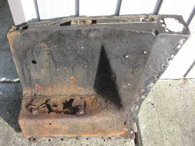
This is how the old inner fender apron looked:

And the hole it left behind before installing the new apron:

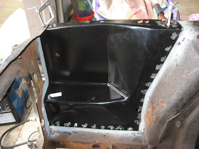
This is the new apron test-fitted with clamps. Holes drilled for the plug welds.

The plug welds are done but unground.

Fresh plug welds from the front.


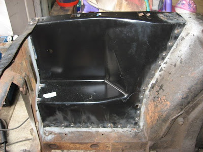
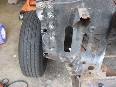
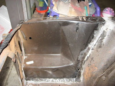
Ground down the plug welds on the inside...And on the core support through which the apron edge flange is welded.

There are a few pinholes left from gaps in the plug welds that I need to fill and grind. Then a coat of primer and this part of the job is done.

Upper Fender Apron Repair 2

While still awaiting my new right front inner fender apron, I continued my repairs to the rust spots on the upper shock tower area where it mates with the right rear fender apron. This one was going to be more tricky since I wasn't removing the entire inner fender apron this time. This meant that I had to cut out patches for the upper (fender apron) and lower (shock tower) sheet metal.

This is how it looked before the repair. The upper shock tower metal is underneath the rear inner apron panel. The rust is where they overlap in the middle of all of the spot welds (the dips in the metal around the rust).


I cut out first a larger section from the top metal (the fender apron) and then a smaller section from the lower metal (the shock tower) . The shock tower metal was of a thicker gauge (14 gauge) than the inner apron (20 gauge).

First I patched the shock tower with a 14 gauge sheet metal torque box section I had laying around and sprayed it with weld-through primer.

Then I cut a patch out of 20 gauge sheet metal. I actually cut it out of the Canadian repro right front inner fender panel I was unhappy with in an earlier blog entry. Note the holes drilled for the "plug" welds. I drilled them in the same location as the original and then cleared the primer off of the area below (on the shock tower) where I would be making the plug welds later.

I welded in the inner fender patch and then plug welded the holes and then ground the whole kit-n-kaboodle down . Notice that I kind of skipped to the end here so to speak. Well, I had some trouble learning how to weld the 20 gauge sheet metal and things got ugly requiring some patching and extensive grinding. No need to show you EVERYTHING I do right? ;-)

And then hit it with some weld through primer although this particular area didn't have to be weld-through, in fact I should have used metal etching epoxy primer instead.

Upper fender apron repair 1

While awaiting my new right front fender apron panel, I decided to patch the front right upper shock tower rust hole that was left after I removed the original apron panel. The rust actually attacks both the shock tower area as well as the fender apron where the spot welds attach them together. However, since I was installing an entire front apron panel, I didn't have to patch it and thus got to kill 2 birds with one stone (the upper apron rust spot and the battery tray rust spot). For this hole, I only had to patch the upper front right shock tower sheet metal.

First I marked out around the deteriorated area making sure the cutout was as perfectly square as I could get ensuring the least pain for cutting a patch.


I cut on the dotted line with my air cutter.


I then measured the hole exactly with calipers and cut out a patch a few hundredths smaller from 14 gauge sheet metal I had from a torque box section I bought and wasn't going to use.

My first weld with my new Millermatic 140 welder. It penetrated just about perfectly using the AutoSet function. I just wish my hand wasn't so shaky making the bead.

I ground the area down smooth with my handy-dandy angle grinder.


Finally, I hit the area with some weld-through primer for assembly.

The Battle Begins - Front Right Inner Fender Apron

This is the sheet metal section in the engine compartment where the battery tray is mounted. It was rusted through pretty bad so I decided to draw first blood by removing this panel and trying my hand at spot weld removal.

Basically, there are a ton of spot welds holding this thing in the car. A weld every 1.5 inches or so. "How do you cut spot welds?" you might ask? Well, with a spot weld cutter of course.

This cutter makes pretty quick work of a spot weld. The point in the center doesn't allow the cutter to cut deeper than about 14 gauge. I pre-punch the center of the spot weld with a spring loaded center punch to make a divot for the cutter point to ride in so it doesn't wander around and I dip it in lubricating oil every couple of spot welds to keep it from wearing out too fast. When I was done, a hunk of car was missing.


I posted a message on Vintage Mustang Forums (VMF) to request an opinion as whether or not to purchase a Canadian make of replacement panel. The thread initially indicated 'yes' but later changed to 'no'. Too late, I'd already purchased the panel which soon arrived was really not the right size or shape. NPD graciously offered to replace the panel with an import panel free of charge so I awaited the new panel.

An Essential Tool

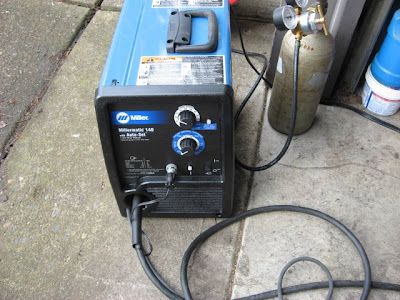
So I rationalized it this way; I saved thousands of dollars by doing this project myself instead of paying someone else. My old welder just wasn't going to be tolerant of the thinner sheet metal segments that would need replaced and patched. My old welder, a Schumacher Turbo MIG 105, has only 4 heat setting that are set via a chunk-chunk type of switch. From my past 10 years of experience with this pain in my posterior, I've decided that it would make the task at hand a living hell so, I was authorized by the SWMBO to budget in a replacement. Last week I picked up my new Miller Millermatic 140 AutoSet welder. It wasn't cheap but it will last for a lifetime, and welds smoooooth.


Oddly, the welder came with .024 wire and .023 tips? I went out and purchased .023 wire from Harbor Freight. Now, I'm not sure if I trust HF welding wire but I tested it quite a bit and it seems up to the task at about 7 bucks a roll. I already had a gas bottle and regulator. However, my bottle contained 100% argon and the Miller also came with a new regulator so I took the bottle in for an exchange of 75%/25% Argon/Co2, hooked up the new regulator and started practicing. Man... this new welder works soooo much better, I can't even describe it. The AutoSet function really does seem to work. Now I need to find a sucker willing buyer to take the Schumacher off my hands (hey! comes with a regulator!)

Don't sweat the small stuff.

In addition to the major floor damage, there are some more minor rust issues that need to be addressed. These minor issues were quoted at around $2000 to repair in themselves. I decided that I need to start here to break in my new "classic car restorer" hat. Firstly, there's an area around the upper edge of the engine compartment where the fenders are bolted to. This is the called the upper inner fender apron or referred to as the upper shock tower area. Each side of the inner fender apron (engine compartment) is basically make up of 3 panels. Front, Rear, and shock tower (center). It's in the strategic locations where ford spot welded these panels together (a circle of about 7 welds) that rust forms. There are 2 of these areas per side for a total of 4 potential rust spots. My Mustang came with 3 rusted through but I only took pictures of 2.


Secondly, there's a shelf where the battery tray fastens to the front right inner fender apron that rusts out due to battery acid and being a generally good place for water to pool. Mine was no exception.


Finally, there's a place on the lower front outside frame rail where the front bumper bolts onto the car. The frame rail in this area is a hollow C-channel hunk of metal with a flat plate section spot welded to the outside section to form an enclosed box. This flat plate houses 2 captive nuts welded into it into which the bumper brackets bolt on. The section that was in contact with the bumper bracket between the two nuts popped in my hand when I was air-hammering scale rust off the frame rail. This is a "normal" area of damage, however, it's normally on the passenger side where it fails due to being below the battery. Mine failed on the driver side instead but the passenger side is fine.


These areas are where I'll initially focus my attention. They're not structural and repairs will be generally hidden if things go terribly wrong. Plus I'll get to practice drilling spot welds and practicing my plug welding skills.

Mustang's are of unibody construction and are assembled out of sheet metal panels that are overlap spot welded together. It's my job to remove these spot welds to separate these panels and then to reattach them using a method that simulates spot welds by drilling a hole in the top panel and filling the hole by welding a "plug" of material into the hole onto the bottom panel thus securing the panels together.