Adsense review

Tuesday, February 24, 2009

Removing the Rear Differential

The floor is done! Woo-Hoo! Major celebration right? Take the car to the painter right!? Right? right? WRONG!

I've got an little problem with my rear-end, you see, it's all brown, flaky, and makes embarrasing squeaking noises. I'm speaking about, of course, the junk beneath my trunk. The area under the trunk at the back of the car was not spared the destructive salt of the NorthEast winters. Fortunately, it's not so bad that it's become cancerous, and although the frame rails are pitted, they still have plenty of meat left to them and can be saved. My plan of action is to grind off the flake rust and treat the problem with Ospho and ZeroRust.

Before I could begin that phase, however, I needed to remove the rear differential because, A) it's in the way, and B) it's ugly too, and C) the leaf springs that hold it in place are rusted pretty badly and their spring has sprung.

The first task at hand was to remove the shock absorbers. These were held on by 2 nuts, 1 accessible from below the shock and spring plate, and the other was accessible from access holes in the rear seat back. The problem with removing shocks was that they tend to spin when you try to loosen the bolts. I solved this by holding the shock housing with a pipe wrench.

Here's a shot of the spring and shock mount plate. This holds the differential to the springs via U-bolts and provides a lower mounting point for the shock. You can see that the differential is resting on jack stands. I tried to adjust the jack stands to provide support but put as little tension on the leaf springs as possible.


This is a shot from above the differential tube showing how the U-Bolts attach to the shock and spring mount plate.
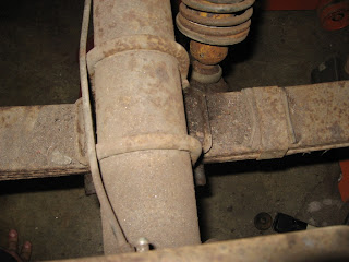
After the shock and 4 big U-bolt nuts were removed, the differential was pretty much free to move about the cabin so I jacked it up slightly higher, readjusted the jack stands, and moved it a bit forward to get it out of the way while I removed the rear shackles (which came out easily since they are mounted in rubber bushings). I then moved the differential/jack stands back as far as I could to allow me as much room as possible to work on the front spring mounting bolts. I supported the spring with a nylon strap so that it wouldn't fall on me when I removed the spring mounting bolts.

Here's a shot of the rear differential suspended on jack stands. I could have man-handled it down and out, but lacking a good way to balance it on my floor jack and maneuvering it out the rear and then sideways, I decided to leave it for the time being until the springs were out.

So, the question bouncing around in your head by now might be something like, "Why did you need so much room? Why was removing 1 simple, solitary bolt such a big deal? Why do I smell like fish?" The answer to the first 2 questions is that the god*!&!, mother@#*!), piece of s&@! was rusted into the hardened steel sleeve in the rubber bushing and no amount of pounding, cursing, coaxing, or clever devices was about to remove them.

In all honesty though, there are several methods to remove these sumbishes depending on the tools at your disposal. One popular method that has worked for many others is to make a pressing tool out of some readily available parts from Home Depot. This method didn't work for me because the convertible inner rocker only allows about 1/2" of working space to the end of the bolt. You could cut the bolt to gain some room of course. This thread on the Vintage Mustang Forums is also helpful and the entry regarding using a Tungsten Carbide sawzall blade was my method of choice. Why Tungsten? Because the sleeves into which the bolts are rusted happen to be hardened. I learned this with the quick demise of 2 innocent bi-metal blades, may they rest in peace and Tungsten blades are pretty much the only thing short of a torch that will cut them. After about an hour per side of cutting, resting, cutting some more, and then resting some more I got 2 things; I got the bolts cut and I got a new respect for people that cut through jail bars with a butter knife.

This is a shot of the tungsten blades and the spring they conquered!

Here's what holds up the back end of the spring. See? Bolts through rubber bushings, no rusting involved and easy to remove. Ah... the good old days.

Here's a little problem waiting to happen that I uncovered. There's a big crack in each of the shock and spring mounting plates. That can't be good.

After I removed the springs, I lowered the jack stands and slid the stands and differential out the passenger side wheel well and then moved the differential to it's new home outside, wrapped snugly under a tarp.

Sunday, February 8, 2009

Welding-In The Seat Platform

After grinding down the umpteen million welds of the floor up to this point there were some imperfections and pinholes in the welds that needed to be filled. I went down to my local NAPA and bought a selection of items. Dupli-Color red oxide primer filler, 3M body filler and NAPA house brand red oxide glazing putty. I tried a little of each on test areas on the inside bottom of the tunnel to test their filling, convenience, color, and durability. I found the easiest to work with was the glazing putty because it could be squeezed out of a tube, spread with a putty knife, dries rapidly, and sands easily. If I were filling large voids or what have you, I would go with the 3M since it's a more durable 2-part concoction.

I filled the few pinholes around the various welds that I had made in the toe boards with the glazing putty and also evened out the seam welds a bit and then sanded the excess putty away.

I then re-applied primer to all of the exposed metal and putty and then attempted to blend the new shinier primer with the old floor primer by roughing it a little with some steel wool. As you can see, the blending attempt didn't go too well but that's okay, primer is primer.

Re-priming the floor was an important step because any exposed metal would be forever exposed between the soon-to-be-installed seat pedestal and the floor where moisture could become trapped and rust through any unprepared areas.

Having completed that step, I could now focus on preparing the new seat pedestal for installation. I laid out the plug weld hole pattern based on my 1968 Mustang Weld & Sealant Assembly Manual and spent another hour or so center-punching and drilling holes in the flanges.

I then fit the seat platform such that the seat rail holes in the seat platform lined up with the access holes on the floor/lower reinforcements. I then gently "massaged" the flanges of the platform flush with the floor using the surgical precision tool: the dead-blow hammer. I marked the seat platform flange locations on the floor so I could remove and reposition the platform. I then used the markings to determine the locations of the various seam welds over which I ran my grinder to expose metal to weld to.

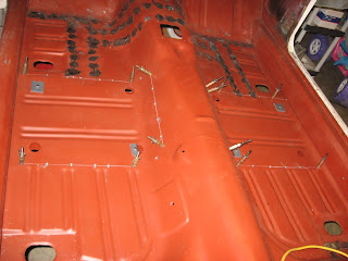
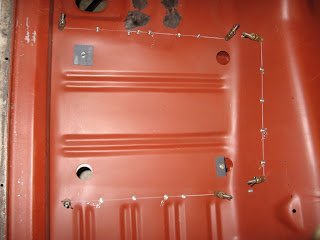
I repositioned the seat platform, and then used a flat-end spot weld bit through each of the holes to expose bare metal to weld to and drilled 1/8" holes anywhere I felt the need to pull the flange tight against the floor for the insertion of clecos. Note the use of clamps at the front and long bolts through the seat rail holes to initially hold the platform in position before inserting the clecos.

I was finally able to begin welding the 46 plug welds that affix the seat platform to the floor. These welds went really well and came out flush with the seat platform flanges such that I have very little weld grinding to do to finish and the seam welds turned out nice too if I may say so myself. It's too bad I'm finally getting a handle on this welding thing right towards the end of the project. ;-)

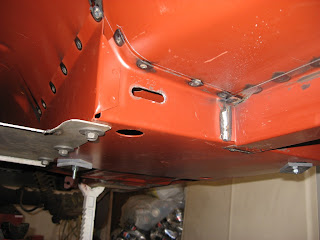
Here's an image up through one of the seat rail bolt access holes. This shot also exposes a shameful secret; a skeleton in my Mustang chamber of horrors, an evil misdeed that surely will have repurcusions through the generations. I' m speaking, of course, about the undersides of the welds you see in the photo. They are NOT on the flanges of lower seat reinforcements where they belong. The flanges should align between the seat platform and the lower seat reinforcement panels and my reinforcements are too far back. This error was conceived way back when I was welding in the front floor supports (frame rail extensions) OR I may have welded in the new floor 1/4" too far forward. I think the latter since I positioned the front floor supports based on the position of the original lower seat reinforcements. Either way, I'm thinking that the front floor supports could actually be welded in after the floor and lower seat reinforcements. I can't think of any welds you wouldn't be able to get to if you were to weld them in last.

Whew... now that I've confessed that, I feel like a huge weight is off my shoulders. In fact, I'm in a confessin' mood now. So check out the picture below. If you can't spot the error, please leave the room and forget I said anything. What the rest of you saw was that the flange on the lower left side of the picture is tweaked way in towards the inner rocker to allow it to be welded. Why? I'm not entirely sure but I figure it's one of the following:

  • The seat platform is at an angle, which I don't really believe this because all of the other ends flanges meet the inner rocker correctly and they wouldn't if the entire platform were crooked.
  • The entire floor is crooked causing the seat platform to misalign which I also don't believe because of the reason above and the fact that the floor settled onto the front and rear tunnels without a problem.
  • The left rocker is 1/4" angled outward. Maybe. This could have happened when I was forcing the front torque box/inner rocker into position.
  • The seat platform itself is made wrong. Maybe, but I'm sure I wouldn't be the only one who this has happened to.

Despite the errors above, I'm pretty sure the car will still drive in a straight line. If not, please let me know now so I can have it crushed. Thanks.

Sunday, February 1, 2009

Welding In Lower Seat Reinforcements

At the end of my last entry, I had marked the positions of the plug weld holes and had drilled the holes through the floor so that I could weld down into the new lower seat reinforcements.

The next step was to re-fit the new metal to the underside of the floor using the alignment marks I had previously drawn. The left and right lower seat reinforcement panels were installed together at the same time joined by the tunnel reinforcement plate. The through-hole clamps were inserted into seat track access holes and tightened up. I then drilled 1/8" holes into centers of the 3/8" holes at the ends of each reinforcement flange and inserted the Clecos that had proven so useful during the floor installation stage. The Clecos were drawn up tight such that I really didn't need the bolts in the seat track access holes anymore but I left them for good measure. I also installed clecos along the panel flange that contacts the inner rocker on the underside of the floor.

The final preparation step before welding was to use a flat-end spot weld bit to expose fresh metal on the reinforcement panel flanges through the plug weld holes.

Finally, I could begin welding. I welded each of the holes in a kind of alternating pattern, like you would use to torque wheel or cylinder head bolts. It's probably not necessary but my gut feels that it helps with heat distribution. I've been using similar plug welding patterns throughout the car.

On the underside, I seam-welded the ends of the front floor reinforcements (frame rail extensions) to the new lower seat reinforcement panels...

... and welded along the bottom of the inner rocker.

I ground the welds on top first using the course grinding wheel and then moving to the 60 grit flap disc. Since the seat pedestal is going to cover this area, I needed to grind the plug welds flush but there's really not a need to make it smooth... well, I guess that technically there's no reason to make any of the floor pretty because it's all going to be covered by carpet but dammit, I just can't help myself.

Finally, I ground down the welds on the lower part of the inner rocker because they will be seen by brake, muffler, and oil change guys and do I really want THEM to think I can't make a pretty plug weld? Hmm? I think not.