Adsense review

Sunday, June 24, 2012

It's ALIVE!

After I had dropped in the engine and transmission, the task of hooking up all of the odds and ends.  A couple of the more odd ends were the transmission cooling lines.  Like the Fuel and brake lines on this car, they were patched together and poorly bent with kinks.  A new set of lines is around $40 from various parts houses plus oversize freight charges.  So, of course, I went down to my local NAPA and bought 5/16 brake/fuel line for about $12 and a tubing bender from Harbor Freight for $7 and set to making my own based roughly on the crappy set I already had.  Yeah, they're not concourse by any stretch of the imagination but they were cheap!

Old crappy trans cooling lines.

Newly bent lines (trans end)

Newly bent lines (radiator end).  I was just using my old radiator to fit the lines.
Speaking of crappy old car parts, I had cleaned up my original radiator in preparation for paint. Just for giggles, I rigged up my garden hose to pressure test it and I'm glad I did because my test exposed a crack in the top tank. I found a guy here locally whom still repairs radiators and offered to rebuild my original for $150. I thought this was a great deal because he would also "rod" it and test it further so I could have an original radiator with original part numbers AND peace of mind. I called him a couple days after I dropped it off and he gave me the bad news that even with a new upper tank the core was beyond saving. I had a choice between doing a core replacement for $240 or buying a brand new radiator for $200 so I opted to give up on the original and get a new one. I brought it home and hooked it up with new concourse hoses I had previously purchased but used modern clamps since the correct original wire-style clamps were $8 each. I figured I could buy those at a later time and swap them out without draining the coolant whereas replacing the hoses later would.

New Radiator

New radiator, hoses, and trans cooling lines.

I was putting the install of the carburetor off because I was nervous about my float settings and adjustments.  Finally, I decided that stuff could always be adjusted when it's on the car so I threaded in the carb mounting studs and slapped a Fel-Pro gasket against the intake.  The spacer plate and PCV hose was dropped on followed by another gasket.  I threaded the choke heat tube onto the choke housing of the carb and placed it on the studs being careful to insert the lower heat tube nipple into the passenger exhaust manifold and fitted the choke cold air tube to the top of the carb.  The upper heater hose was fitted stuffed into its clamp next to the choke housing and the throttle linkage was hooked up to the throttle control.  I'm using my original AutoLite 2100 throttle spring and bracket but will be getting the correct parts later.

Finally, to complete the engine build, the distributor wires were routed to their appropriate spark plugs.

Carb studs and intake gasket.

Carb spacer and carb gasket.

The carb.

Choke heat tubes and upper heater hose.

Manifold shot of the choke heat tubes.

Engine ready for start-up.

All that work on the transmission cooling lines is wasted if I don't have something for the transmission to do.  Something like, I don't know... maybe spin the rear differential?  I went to the shed and dug out my old drive shaft.  I don't know much about drive line lore except for this; a 68 Mustang with a 289 driving a C4 and sporting a stock 8" rear diff uses two different u-joints.  The front is a #429 and the rear is a #430.  The front (429) has 1 1/16" diameter caps whereas the rear (430) has two 1 1/16" and two 1 1/8" caps. 

The rear of the drive shaft is the end with the rubber isolator and the smaller caps (1 1/16") of the #430 u-joint are pressed into the drive shaft leaving the larger caps to be clamped to the rear diff pinion.  The front u-joint is simply pressed into the drive shaft first and then the yoke is installed the same way.  It doesn't matter which caps go in which part in the front yoke assembly.  The drive shaft can then be installed in the car by first inserting the yoke spline into the extension housing of the transmission and then seated in the diff pinion and clamped in.  The pinion has ridges on the outside edge that keeps the caps in position so clips are not necessary on the two large caps.

Using a bench vice to press the caps onto the new u-joints.

Using a socket to push each cap in enough to put on the clips.

Rear u-joint.

Drive Line in place.

Next, I cobbled together the original single exhaust and bolted its Y-pipe to the headers.  It's rusty, leaky, and ugly, but I can't afford my planned dual-exhaust yet so it's going to have to do.  I didn't snap pictures because they would just depress you.

I was finally to the point of pouring the first four quarts of oil into the engine and pouring the first 2 quarts into the transmission (in addition to the 2 in the torque converter).  The radiator was also filled with a 50/50 mix of coolant and about a gallon of gasoline was poured into the gas tank.  I checked for leaks and found a slow drip at the front of the transmission pan.  A few strokes of the wrench and it sealed up.

I disconnected the coil and cranked the engine over about 10 times to pump some fuel up the line and to move the oil into the pump to begin lubrication.  This was enough to fill the oil filter so I added the final (5th) quart of oil to the engine and topped off the transmission and coolant.  Nervously, I called my wife out to witness and cranked the engine over.  Nothing.  I poured a small amount of gasoline into the carburetor and tried again.  It caught, missed, caught, fired, died, caught, and finally fired up... very very roughly, like it was missing on a couple of cylinders.  I shut down and went and inspected the carb, distributor, and distributor wires.  Whew!  I found that I had mixed up 1 and 4.  I swapped them and fired it up and she came to life with authority.  Clean, with no missing cylinders.  WOOT!  I set the carb for a high idle, about 2000 RPM and settled in for some serious cam-break-in time.  That's about when my wife yelled, "TURN IT OFF!".  I scrambled for the key yelling, "What!? What!?", fully expecting to see a fire or something at which point she pointed at the coolant blowing out of the radiator.  I didn't put the cap on because I wanted to add coolant as it started circulating.  I put the cap on and started it and brought it up to about 2000 RPM again to complete the break-in and it started blowing coolant out the overflow and all over the garage floor.  WTF?  I removed the radiator cap and placed a funnel I had made out of an oil can into the filler and watched bubbles burp up the funnel and the level would drop and then rise again as another bubble came up.  Ahhh... it's burping the air out of the engine block.  I just left it to burp for another 5 mins and then topped off the coolant and started it again but this time with the overflow feeding a gallon jug as I fully expected it to occur again until the block was fully burped.  I fired it up yet again and held it at it's 2000 RPM for a good 30 minutes with no sign of further overflow (undoubtedly because I was ready for it).  My wife then snuck in with a video camera and recorded the less exciting moments of break-in which I will share with you here.


After the cam break-in period, I shut it down, topped off the fluids again, and decided to try to test out the transmission by taking a spin around the cul-de-sac.  It was working out pretty cool until I got about 3/4 around and the engine died and wouldn't restart.  Evidently, had I used what little gas I put in the tank on the break-in and my hilly driveway and cul-de-sac starved the engine.  I had fun while it lasted though.  Notice the cool new sequential brake-lights about half-way around.  Here's a VMF thread I found AFTER the break-in.  There seem to be a lot of tips.


Tuesday, June 19, 2012

Catching Up

I was getting pretty far into the build and remembered that I hadn't done a blog entry in awhile so I thought I'd catch up a bit.  I may break this into several pages at a later time.

The rebuild and install of the 
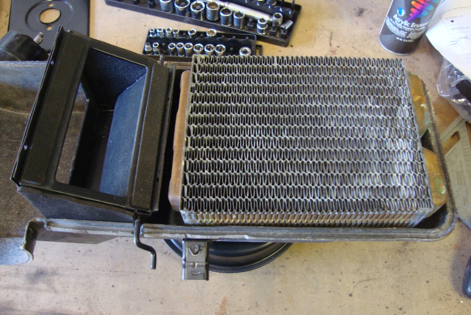
heater box wasn't just the completion of the under-dash but also the beginning of the completion of the engine compartment because it meant that the remaining holes in the firewall were now filled.  Now, the next step seems pretty straight forward but I procrastinated it for a couple of days until I could come to terms with what had to happen next.  All the firewall penetration points needed to be sealed and the firewall in general, needed to be uglified because that's how the factory did it.  If the factory jumped off a cliff would I?  Probably, but with much introspection first.  The problem was that, in my eyes, my firewall was a thing of beauty.  Ten times the glory of Helen of Troy, 30 times the beguile of Cleopatra, and 50 times the charm of 
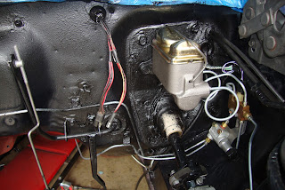
Laura Kaeppeler.  So, understandably, I cried a little when I smeared a tube of sealer all over every nut, bolt, and rubber plug on my once-pristine firewall.  As if that weren't enough of a crime, I followed up with shots of 3M rubberized undercoating.  I should be jailed for this travesty.

Oh man, I think I'm going to be sick...

Nooooo!

Also, I installed the ash tray and glove box.  No radio yet because I want to weigh my options a bit more.  The steering wheel was installed and wired in.

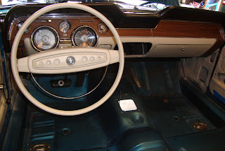
Looks almost like  it's ready to drive.
My attention could be turned back to the engine.  I installed the backing plate and the flex plate.  The transmission linkages and mounting brackets were installed and I poured two quarts of Dextron III.  Yes, I'm using Dextron in this C4 (kids, don't try this at home).  Fact is that C4's traditionally use "F" type fluid.  This serves two purposes.  The first is that it didn't attack the old-fashioned organic friction surfaces and seals like the other leading brands but I've replaced all of the clutches, bands, and seals in this C4 with modern materials.  Secondly, "F" fluids have less "friction modifier" than Dextron thus provides a better grip to the old fashioned friction surfaces.  Too much slip in an old C4 with organic clutches will burn them up.  I'm not worried about that for these new clutches.  The friction modifiers in DIII may cause the shifting to become "looser" but I'm not convinced that's a bad thing yet.   If shifting proves too sloppy, I'll replace it with "F".  Some racers use a 50/50 mix of "F" with Dextron to provide a good balance between viscosity and friction with no ill-effects to the trans. 

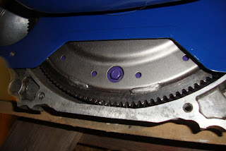
Aaaanyhoo, I poured 2 quarts into the new (purple?) torque converter (TC) and carefully seated it on the input shaft of the C4 making sure to wiggle it and adjust it until it was fully seated on the input shaft, the pump stator, and the TC hub to pump.  Regarding how much fluid to place in the TC, my research revealed that the TC could technically be left empty because the C4 pump will fill it within seconds.  I also, found more conservative info stating that the TC should contain a couple of quarts so the internal vanes don't spin dry.  I went with the conservative method.

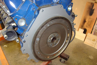
Engine plate and flex plate.

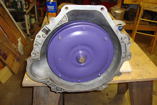
Barney The Purple Torque Converter  (I spin you, you spin me...)
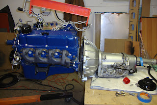
Next the engine was mated to the TC.  This is a tricky bit but I learned some tricks that worked very well for me.  Firstly, the TC is spun to align one of the drain plugs at the bottom of the bell (see above).  Secondly, the flex plate on the engine is rotated to align one of the drain plug holes at the bottom of the engine.  You can use a short length of tubing over the bottom drain plug screw to help when you align the TC to the flex plate but it wasn't necessary for me.  Also, you can temporarily screw a stud into one of the engine trans bolt holes to help align the bell to the engine block.   This was another thing I didn't need to do.   What I did need to do was to place the C4 on the edge of a table while I lifted the engine with an engine hoist and load leveler and butted it up to the transmission making fine adjustments in position as needed.  I think I was channeling old Henry himself from what I've read of others bad experiences with mounting engine to C4 but for me this was literally a non-event.  The two practically jumped into each others arms like two star-crossed lovers.  It was like, *wiggle* *wiggle* *thunk!* and it was done.  I inserted the bolts and finger-tightened them until they were all seated and the gap was closed.  No force required.

Once the bolts were in, I torqued them to spec and then rotated the flex plate to access each of the four TC studs and tightened them in turn.  The engine/trans was placed on a tripod of three jack stands.  One under each motor mount and one under the C4 extension housing where I installed the starter and stored the assembly for a few days until ready to drop it into the car.

Aligning the engine to C4

The Eagle has landed

The alignment of the lower drain plug with the flex plate drain plug hole.

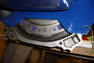
Flex plate rotated to install the TC nuts
A few days after mating the engine to the C4, I was ready to commit to the installation of the engine into it's home for the next 40 years.  I backed the car out of the garage to leave myself enough headroom to lift as high as I need to.  My garage is weird and has some beams hanging low across the ceiling due to my garage being under living space of the house.   Also, it's recommended by many that the back end of the car be lifted to aide in the alignment of the transmission into the tunnel.  However, I couldn't do that because of the way my driveway is built.  I felt it unsafe to lift the back of the car given the screwy terrain.  Fortunately, I had a load leveler but I decided to experiment in its use with a carb lift plate that bolts to the carburetor mounting holes.  It did work but the leveler had to be adjusted all the way from end to end to get enough angle on the engine given the short distance between the front and rear mounting points.

Regardless of the issues, my helper (thanks sweety!!!!) held the C4 extension in line with the tunnel while I pumped the hoist and cranked the leveler.  After about an hour, we managed to get it down into the engine compartment and aligned with the engine mounts.   Some fine adjustments allowed the two mounting bolts into place.  The rear of the C4 was supported by a rolling floor jack during the final few minutes to level the engine up and support it while the transmission cross member was installed.

Starting the drop

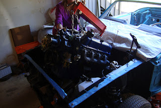
Getting there (thanks helper!

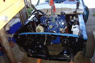
Alllllmmmooooossstttt there
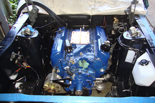
It's IN!

Transmission cross member.
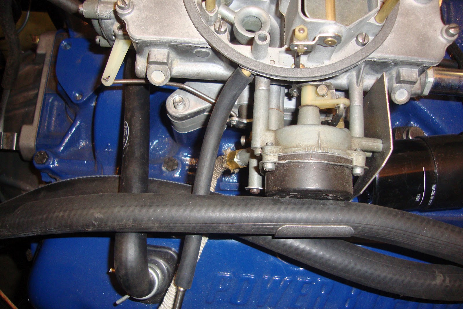
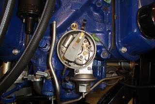
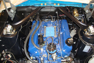
I next hooked up controls that I could such as the trans to throttle kick-down, the speedometer cable, the vacuum modulator line, the fuel line to pump, heater hoses, coil, battery cables, engine gauge harness, neutral safety switch, and the pump cooling fan and pulley.  Additionally, the distributor was installed but first, the engine had to be reset to TDC on the compression stroke.  I confirmed this by removing the passenger valve cover and confirming that no valves are open on #1 and the timing mark was to zero.  The distributor was then marked where the rotor would point to the #1 contact and inserted into the engine block at the point where the gears aligned the rotor to the previously marked #1 position.   The most difficult part was seating the pump shaft into the bottom of the dizzy.

Confirming the compression stroke on cylinder 1.

Dizzy aligned.
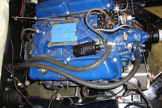
Heater hoses and coil hooked up.

Battery ground and alternator ground cables.

Battery tray with positive battery cable.
The next little project was the installation of the export braces.  A lot of people have trouble with this as the shock towers tend to settle after years and the weight of the engine forces them together a little.  All I had to do to get them on was to mount the shock tower ends first and then jack the engine up at the transmission to engine joint to take the weight off the suspension and engine mounts.  This was enough to get the bolts into the cowl holes and tighten them up.

The export braces installed between the cowl and shock towers.
I then R&R'd the shifter housing via the media blast/paint routine.  I had some spare parts that I'd picked up at swap meets such as a shaft and handle that weren't pitted. I also installed new bushings as mine were completely gone.  After getting the shifter release button working smoothly, I installed it in the car with a gasket between the tunnel and the shifter housing.  I set the C4 to reverse (the indent immediately after park) and set the shifter to reverse and tightened the shifter linkage nut.   The shifter  seems to work smoothly and accurately.

A rusty, pitted, shiftless mess

Cleaned up, painted, new bushings.

Linkage hooked up.

Good to go.

I went so far as to remove the radiator from the shed and clean it up.   I did a simple pressure test using a garden hose and found a leak.  The radiator has since been dropped off at a radiator shop.  Also, a windshield, gasket, and sealer are on order so stay tuned!

Thursday, June 14, 2012

Turning Up the Heat

The last major item that completes the assembly of the dash is a pretty complicated system in itself; the heater box.  This assembly contains a blower motor, a speed control, several air redirection flappers, defrost ports, a water heater radiator core, and a small pile of rubber seals.  To top it all off, it fills the remaining holes in the firewall as well as seats up against the passenger side cowl vent.

Of course yours truly, being an eternal optimist, thought he could just clean it up, throw some paint on the outside, and put it back in.  That is, until I really got to looking at it.  The motor was all crusty, the paper defroster plenum was crushed, and there was a mummified family of mice residing within.  I searched for parts and soon discovered that all of the parts required to rebuild a heater box were available.  The most important, being a seal kit since all of mine were deteriorated long ago.

I placed an order with NPD and began to disassemble the box starting with the removal of the old heater hoses and the removal of the defroster plenum by removing the four screws holding it on.  Next, the clips could be popped off and the box split in half.   Normally, I'd spend the time giving a full set of instructions for rebuilding a heater box but there are already plenty of sources for that: A VMF Thread, A Mustang Monthly online article, a CJ Pony Parts writeup (by VMF member 66FSTBCK), and more if you do some Goggling.  That's not to say I didn't take lots of pictures of the various steps though.

Upon removal of the heater core, I decided to flush it out with a hose tucked up against one of the water tubes.  I ran a lot of water through it until the water became less and less red-tinted.  After that, I checked the core for leaks which is really as easy as sticking your thumb over one of the water tubes and sucking on the other one.   Yes, I said "sucking".  According to more knowledgeable folks than I, you can draw a vacuum of right around 14 bar just with your own mouth.  So use whatever imaginary image that works for you and wrap your lips around that pipe, create a vacuum, and just sit there and wait to see if you can detect any reduction in vacuum over like 10 seconds.  If not, you're good to go, which mine was.  Seriously, there's a web page that describes the process.  Just remember, I flushed the heck of that core first.

Another sub-task that this rebuild required was the breaking down of the blower motor which is removed from the fan housing by removing four nuts.  The fan can then be removed by removing the lock screw from the shaft and sliding the fan off the shaft.  Unfortunately, mine didn't just pop off, I held the fan and tapped lightly on the shaft being very careful not to deform the end.  After the fan came off, I found that the shaft then seemed like it was jammed and I was worried that I'd ruined the motor.  I removed the motor from its mounting plate and pulled the motor apart.  The shaft came free so I blasted the motor shell and repainted it since it was already apart.

The difficult part of the task was cleaning up the mess.  I removed as many metal parts as I could from the box and blasted them.  Then I masked off all of the surfaces of the box except for the remaining metal parts that are riveted on, and blasted them as well.  I used lacquer thinner to clean the fiberglass portions of the box inside and out.  All metal parts were then sprayed with etching primer and semi-gloss engine enamel.  The box was then deemed ready for assembly so I awaited the arrival of the new parts.

Starting Out

Hoses off.

Front View

Top View

Cracked open

Heater core removed.

Flushing the core

Nasty

Mouse mummies.

Remove four nuts to pull the motor

Hex wrench to remove the set screw for the fan.

Gaskets after motor is removed.

Face of motor with number stamps.
Media blasted motor case.

All of the rusty parts.
After the heater box was completely broken down, I ran all of the metal parts through my blast cabinet.  The parts were then primed with etching primer and then painted with semi-gloss engine enamel.  The fiberglass box halves were strategically masked off to blast, prime, and paint the cable brackets.  Then a dab of silver paint was touched on the various rivets to detail them off.

All of the media blasted parts

All of the freshly primered parts

All of the freshly painted parts.

Putting the speed control back in.  Note the use of strip caulk.

Brackets painted and detailed.
The seal kit contains a complete set of foam and foam rubber seal parts.  They're not exactly like the remnants of the original seals but rather better than the originals in that they'll sometimes cover an entire seal surface rather than just strips around the edge of a seal.  The kit came with instructions on where the seals go but my own reference pictures helped with determining more exactly where the old seals were on the original metal parts.  The seals were affixed to the parts using 3M contact spray adhesive.  As with paint, I had to mask off any areas where I didn't want contact cement to be sprayed. A majority of the seals are used on the "flapper box" (as I call it, really, the flapper assembly that switches air into and away from the heater core).

 The box was then reassembled by first inserting the flapper box into the fiberglass section containing the fan.  The flapper box is affixed to the fiberglass box with two sheet metal screws.  The sheet metal heater core support was next laid into position and the inner heater core seal was glued on over the top.  The heater core was set into the seal and the other core seal was glued into the side of the box with the speed control.  The two halves could then be carefully pressed together making sure not to damage the seals on the sides of the flapper box.   The many clips can then be used to clamp the box back together.


Seal installed on the clean-out door.

Seals installed on the "flapper box".

Flapper box installed in the vent-side heater box with heater core seal.

Heater core installed.

Box being reassembled.

Channel locks to clamp the sides together while clip is installed.

 The motor seals are affixed to the mounting plate and the motor is bolted onto it, the fan mounted on the motor shaft, and the assembly bolted back into the fan housing of the main heater box.  Finally, I clamped new heater hoses onto the heater core supply tubes completing the heater box R&R.  I next brought out the heat control panel that's mounted into the left side of the car's dash and adjusted the positions of the cables and marked them on the box with masking tape.  This would allow me to easily position them after the box is in the car without a bunch of fiddling around in the cramped space.

Blower motor mounting plate.

Blower motor.

Fan affixed to the blower motor.

Blower motor affixed to the fan housing.

New heater hoses with original style clamps.

Ready to go in!  Cable positions pre-marked.  The cables had matching markings.

 Finally, the box was worked back up under the dash, the hoses snaked through their holes in the firewall, and the mounting studs through the motor port.  New speeds nuts were used to mount the box to the firewall.  Inside the car, the speed control wires were hooked up and the upper cowl support bolt installed.  The control panel was inserted on the left side of the dash and the control cables snaked up over the pedal bracket next to the firewall and directed to their appropriate bracket on the heater box.  Finally, the windshield defroster tubes were piped into the top of the defroster plenum.

Heater installed in the firewall.


Speed control wires and upper cowl mount (upper right side of picture).  Cables attached to brackets.

Cable attached to defroster plenum.
Heater Controls Installed


defroster hoses hooked up.