Okay, now that I have a
control valve to control my power steering and a
power cylinder to power my power steering, I needed something to squish the power steering fluid (Type F ATF, actually) into the control valve and power cylinder and what better way to squish fluids into things than with a pump? Fortunately, I had made a deal with a
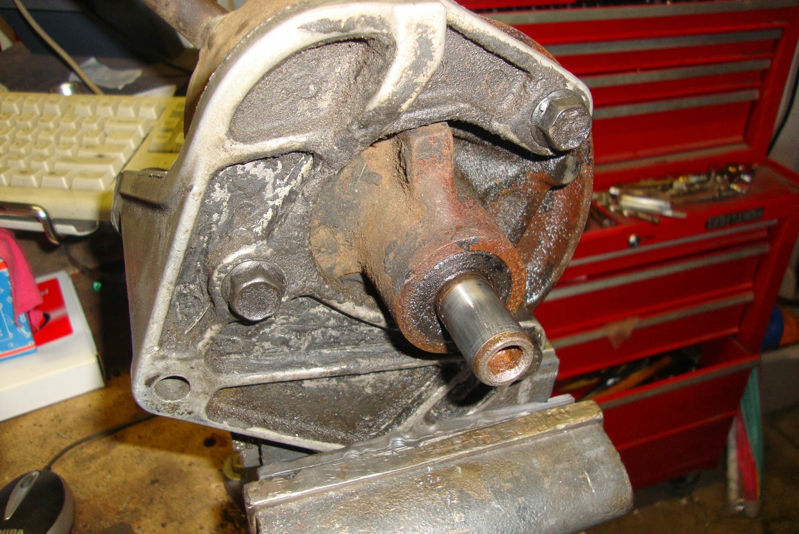
VMF member to buy the entire power steering system including the pump and bracket(s). Unfortunately, the pump was in no better condition than the cylinder or control valve and was in desperate need of a rebuild. Well, I'm not sure it qualifies as a "rebuild" per-se because I didn't replace any of the mechanical parts of the pump. Rather just some spit-n-polish and some new seals placing my faith in the car-gods to protect me. Additionally, I attempted to assess the condition of the assembly by making sure it rotated smoothly, without binding, and that there was no discernible slop in the input shaft. That all felt good to me so I forged ahead.
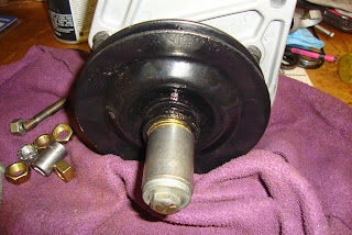
The first part I felt the need to remove was the pulley. This was accomplished with, what else? A pulley puller. There's a protrusion on the front that is intended to be used to pull the pulley off without damaging it. The pulley puller has wider jaws than a regular gear puller. I had attempted to use a gear puller and failed when the narrow jaws just slipped and chipped off chunks of the puller flange edge. I wandered down to Harbor Freight and bought the
Automotive Pulley Puller. After some sweating and cursing at the puller jaws popping off of the flange, I clamped the end of the puller jaws onto the flange with a C-Clamp so it wouldn't slip off and succeeded in removing the pulley.
I could then get to the bolts of the pump bracket and remove the bracket from the pump housing. I then turned the pump over and removed the nut from the high pressure output nipple along with it's id tag. The pump can was then free to be pulled away from the pump assembly. There was one seal washer between the can and the pump.
 |
| In the beginning... |
 |
| Come.... ON... get.... OFF!! |
 |
| The bracket could then be removed. |
 |
| The nut removed from the pump outlet |
,,
 |
| The can has been removed. This washer prevents leaking from the base of the pump outlet. |
 |
| Pulled apart. |
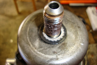
Four bolts could then be removed and the back of the pump was removed to expose a stack of pump parts that were kept in place via two locating pins. The stack of parts just lifted off of the pins until the end of the input shaft was found nestled deep within the pump rotor. The shaft could then be pulled up and out of the front pump plate. Since the end of mine was rusted a bit from exposure, I had to polish it with a wire wheel to allow it to be pulled out through the front bushing.
 |
| Removing the inner can from the pump front. |
 |
| Split apart |
 |
| Unstacking the pump rotor assembly |
 |
| Looking in at the rotor |
 |
| How the rotor is removed from the front plate. |
 |
| Pulling the input shaft out of the front plate. |
After the shaft was removed, the front seal could be popped out.
 |
| Removed the front seal. Make sure the bushing beneath is still serviceable. |
Next the pump stack was thoroughly cleaned and pre-lubed with ATF and then reassembled in the exact same orientation using several pictures I took of each part being removed. The input shaft was polished using a brass wire wheel and steel wool.
 |
| Removing the relief valve from the inner can |
 |
| Rusty shaft |
...
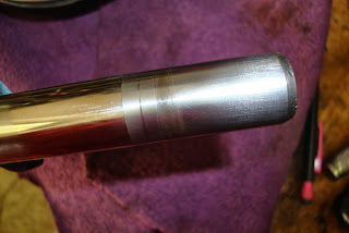 |
| Cleaned up shaft |
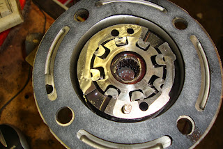
Probably the most puzzling part of the re-assembly was the placement of two springs in the bottom of the pump can onto which the relief valve puck was placed. If the springs toppled over, the puck would have to be removed and another attempt be made. I re-assembled the pump kind of backwards from how I took it apart. That is, I stacked the parts in the can then mated the shaft and pump front onto it.
 |
| The ends of the springs go into those round protrusions |
 |
| Relief valve puck installed. Note the alignment of the slot in the side of the can in relation to the ports on the puck. |
 |
| Rotor assembly installed. |
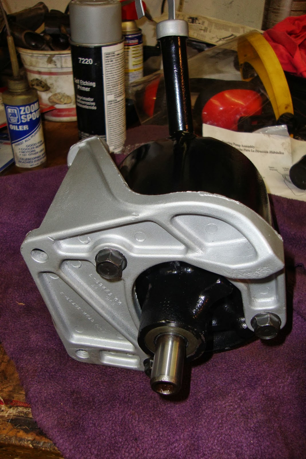
The pump housing was then cleaned up, primered, and painted semi-gloss black. Now calm down, I DID research the correct factory color of the 68 power steering pump and what I came up with was... well... I found a VMF thread that debated it a bit.
You read it and choose your own pump color. What I came away with was that it was just as likely that you get a black pump from the factory as a teal/blue pump so that's what I went with since I had black paint handy, needed to paint it NOW, and didn't want to wait for the factory correct color... so there. If you have the time to wait, the consensus of respectable Mustang gurus on the web is that
NPD has the closest match.
Aaaanyway, after the housing was painted, I drove in a new front seal. If you have any play in your input shaft, replace the bushing as well. I didn't, so I didn't.
UPDATE 3/20/2015: It's been pointed out to me that if you've gone this far, you may as well replace the bushing. I was admittedly lazy with this step. In order to truly assess the condition of the bushing would likely require the use of a micrometer.
 |
| De-rusted |
 |
| Self-etching gray primer. |
 |
| Semi-gloss black engine enamel |
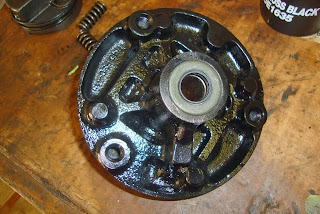 |
| New seal inserted |
Oh yeah, speaking of the front seal, it came in a seal kit that I bought
from NPD.
 |
| Mating the front of the pump to the inner pump can. |
 |
| Touch down. Torqued. Note the alignment of the intake slot against the slot in the edge of the relief valve puck. |
 |
| Assembled pump |
 |
| New can ring gasket |
When the outer pump can is placed against the front plate, there's a particular way it has to be indexed. It will fit in ANY direction but has to be installed in just one orientation. The key is to have the intake slot on the inner pump can facing down.
 |
| Inserting the outer can onto the pump. The input slot on the inner can wall faces down. |
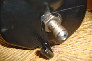 |
| Tightened down the pump outlet nut. |
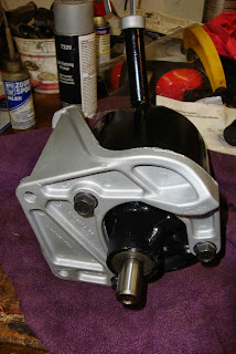 |
| Installed the freshly painted bracket. Notice the orientation of the ridges on the pump front casting in relation to the fill tube. This orientation is important. |
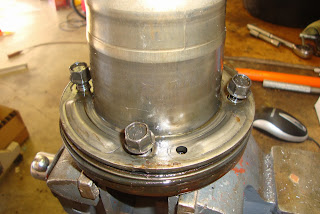
After the pump was re-assembled, the pulley needed to be pressed back onto the shaft. The inside of the shaft is threaded so I stacked up some greased washers and a socket and pressed the pulley back onto the shaft so that the end of the shaft was flush with the puller flange.
 |
| Pressing the pulley back on |
 |
| Installed |
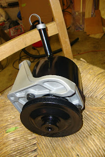 |
| Done. |
The pump was then deemed ready for service. Now I just have to see if they can all work together as a team.